GPS for accurate synchronization and position measurement must use precise clock, so GPS satellites are equipped with atomic clocks. Clock accuracy is amazing ± 1 second in 1 million years. Using GPS module is available not only acquire position, speed, bet also time and date, so in this post I’ll explain how to do it.
GPS clock consist of old Sirf II GPS module, MAX 232, Arduino Mega and LCD display (Hitachi HD44780).
Sirf II module has RS-232 interface for communication and it can be connected to PC Com port. Atmega in Arduino board has UART interface. RS-232 basically is the same UART, only zeros and ones voltage levels are different. To match levels MAX232 driver is used. Today’s GPS modules have UART port, so there isn’t any need for MAX232.
Arduino in this project doesn’t have clock function it just pass time and date from GPS module to display. It works that way because GPS module has internal RTC(Real time clock) it’s not accurate, but it is synchronized to GPS system.
As you can see from video GPS module RTC is sychronised before GPS fix happens, but GPS fix is only one indicator that shows that clock is synchronised.
NMEA protocol
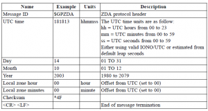
Communication between Arduino and GPS receiver is based on NMEA communication protocol. It uses ASCII symbols. There are input and output messages, example of one output message contained information about current time and date:
$GPZDA,181813,14,10,2003,00,00*4F
Data format:
All output messages are similar and consist of message header, separated with comma values and checksum.
Message can be easy decrypted and date and time values extracted.
Input messages will be used in program code, and here explained.
Program code
Arduino from GPS module periodically will receive NMEA ZDA and GGA messages. ZDA contains date ant time values and GGA gives information about GPS fix and used satellites number.
Each message’s beginning is saved in array for later match with received data in Arduino UART buffer.
unsigned char GGA_id[7]={
  '$','G','P','G','G','A',','};

unsigned char ZDA_id[7]={
  '$','G','P','Z','D','A',','};
Show_time_date function converts ASCII symbols to integers. This is more complex than just sending ASCII symbols straight to LCD display, but conversation allows to manipulate date and time as normal numbers.
Values in NMEA messages always have constant position, so they are extracted just by selecting specific array members.
void show_time_date(void) {

 hour = (((int)buffer[0]&0x0F)*10)+((int)buffer[1]&0x0F);
  minute = (((int)buffer[2]&0x0F)*10)+((int)buffer[3]&0x0F);
   second  = (((int)buffer[4]&0x0F)*10)+((int)buffer[5]&0x0F);

    day = (((int)buffer[10]&0x0F)*10)+((int)buffer[11]&0x0F);
  month = (((int)buffer[13]&0x0F)*10)+((int)buffer[14]&0x0F);
   year  = (((int)buffer[16]&0x0F)*1000)+(((int)buffer[17]&0x0F)*100)
+(((int)buffer[18]&0x0F)*10)+(((int)buffer[17]&0x0F));

    lcd.setCursor(0, 0);

   lcd.print("UCT time ");

  if (show||GPS_position_fix_indicator) { //blinking display
   if (hour<10) lcd.print(' ');
   lcd.print(hour);
   lcd.print(":");
    if (minute<10) lcd.print('0');
   lcd.print(minute);
   lcd.print(":");
    if (second<10) lcd.print('0');
   lcd.print(second); }
     else lcd.print(" ");

    lcd.setCursor(0, 1);

   lcd.print("Date ");
   if (show||GPS_position_fix_indicator) { //blinking display

   lcd.print(year);
   lcd.print("-");
    if (month<10) lcd.print('0');
   lcd.print(month);
   lcd.print("-");
    if (day<10) lcd.print('0');
   lcd.print(day);
   }
     else lcd.print(" ");

show=!show; //blinking display
 }
Similar story with show_status, only there is switch statement to show on display different messages according to GPS Fix status.
void show_status (void) {

GPS_position_fix_indicator = (int)(buffer[36]&0x0F);
GPS_sat_used = (((int)buffer[38]&0x0F)*10)+((int)buffer[39]&0x0F);

     lcd.setCursor(0, 2);
     lcd.print(" ");
     lcd.setCursor(0, 2);
     switch (GPS_position_fix_indicator) {
     case 0:  lcd.print("Wait for GPS fix");
              for (int i=0;iprint(".");
              }
              lcd.setCursor(0,3);
              lcd.print("Sat. used: ");
              lcd.print(GPS_sat_used);
              dot_count++;
              if (dot_count >3) dot_count=0;
              break;

     case 1:  lcd.print("GPS fix OK");
              lcd.setCursor(0, 3);
            lcd.print("Sat. used: ");
              lcd.print(GPS_sat_used);
              break;

     case 2:  lcd.print("DGPS fix OK");
              lcd.setCursor(0, 3);
           lcd.print("Sat. used: ");
              lcd.print(GPS_sat_used);
              break;

   }

}
fill_buffer reads UART buffer and flushes it after NMEA messages end indication.
void fill_buffer (void) {

  while (Serial.available()) {

        buffer

 =<span style="color: #cc6600;"><strong>Serial</strong></span>.<span style="color: #cc6600;">read</span>();
        <span style="color: #cc6600;">if</span>(buffer

==0x0D) {Serial.flush();}

   }
}
Default GPS Sirf II baud rate is 4800bps.
Serial.begin(4800);
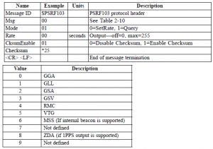
To lower UART port load all NMEA output messages are disabled using input messages.
  Serial.print("$PSRF103,00,00,00,01*24"); //GGA
  Serial.print(0x0D,BYTE);
  Serial.print(0x0A,BYTE);
  delay(10);
  Serial.print("$PSRF103,01,00,00,01*25"); //GLL
  Serial.print(0x0D,BYTE);
  Serial.print(0x0A,BYTE);
  delay(10);
  Serial.print("$PSRF103,02,00,00,01*26"); //GSA
  Serial.print(0x0D,BYTE);
  Serial.print(0x0A,BYTE);
  delay(10);
  Serial.print("$PSRF103,03,00,00,01*27"); //GSV
  Serial.print(0x0D,BYTE);
  Serial.print(0x0A,BYTE);
  delay(10);
  Serial.print("$PSRF103,04,00,00,01*20"); //RMC
  Serial.print(0x0D,BYTE);
  Serial.print(0x0A,BYTE);
  delay(10);
  Serial.print("$PSRF103,05,00,00,01*21"); //VTG
  Serial.print(0x0D,BYTE);
  Serial.print(0x0A,BYTE);
  delay(10);
  Serial.print("$PSRF103,06,00,00,01*22"); //MSS
  Serial.print(0x0D,BYTE);
  Serial.print(0x0A,BYTE);
  delay(10);
  Serial.print("$PSRF103,07,00,00,01*23"); ///////ZDA
  Serial.print(0x0D,BYTE);
  Serial.print(0x0A,BYTE);
    delay(10);
But needed messages are enabled with automatic 1s update rate.
/////////////////////////////////////////ZDA

 Serial.print("$PSRF103,07,00,01,01*22");
  Serial.print(0x0D,BYTE);
  Serial.print(0x0A,BYTE);
    delay(10);

////////////////////////////////////// GGA

 Serial.print("$PSRF103,00,00,01,01*25");
  Serial.print(0x0D,BYTE);
  Serial.print(0x0A,BYTE);
    delay(10);
In my view the most complex code part are in loop.
In first place there is message match. To UART buffer received ASCII symbol are compared to ZDA and GGA messages headers symbol by symbol:
  if (Serial.available() > 20) {

    for (int i=0;iSerial.read();

      if (incomingByte==ZDA_id[i]) {
        valid_ZDA--;
        valid_msg=true;

      }

      if (incomingByte==GGA_id[i]) {
        valid_GGA--;
        valid_msg=true;
      }

      if(!valid_msg) {i=7;} // break from "if" loop
    }
If there is match remaining message part is readed from UART buffer and proccesed with known functions.
    if (valid_ZDA==0) {

     while (Serial.available()delay(10);}

      fill_buffer();

      show_time_date();

  }  /// (valid_ZDA==0) {

      if (valid_GGA==0) {

      while (Serial.available()delay(10);}
      fill_buffer();
      show_status();

     }

  }

}
Download full code:
 Arduino GPS clock source code (5.3 KiB, 9,597 hits)
![gps.mp4_snapshot_01.50_[2010.11.12_18.28.38]](https://www.electronicsblog.net//wp-content/uploads/gps.mp4_snapshot_01.50_2010.11.12_18.28.38-1024x576.jpg)

