This meter gives the best results at 0 – 1000 Hz range. It works by measuring square wave total and high period duration using 16 bit hardware counter.
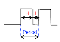
As you may know frequency = 1/Period and Duty Cycle = High period duration/total period duration.
This meter gives the best results at 0 – 1000 Hz range. It works by measuring square wave total and high period duration using 16 bit hardware counter.

As you may know frequency = 1/Period and Duty Cycle = High period duration/total period duration.
LCD in this picture has 2×16 characters, so in quick way horizontal bar could have 16 steps resolution, but it’s not enough. Each character is formed from 5×8 pixels. Every character can be sliced in to 5 pieces. After that we can have 5*16 = 80 steps.
First step is to create 5 custom characters. More about createChar() please read at arduino.cc.
Each custom character is specified by an array of eight bytes. Byte represents character’s row.
![fm.mp4_snapshot_00.42_[2011.02.08_14.45.25]](https://www.electronicsblog.net//wp-content/uploads/fm.mp4_snapshot_00.42_2011.02.08_14.45.25-300x168.jpg)
Old wish to make digitally controlled FM tuner come true when I found on Ebay cheap module with TEA5767 (Low-power FM stereo radio for handheld applications).
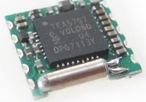
This module size is only 11.2mm x 11mm. TEA 5767 supports I2C. Pinout and wiring:
For antenna i have used just 75 cm long wire, because that is 1/4 of wavelength at 100 MHz. TEA5767 doesn’t have audio amplifier, sound output level is very low, headphone can not be connected directly. During testing i had connected audio output to PC audio system.
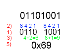
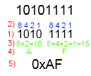
This type of conversion from binary to hexadecimal often needed during microprocessors registers configuration. By reading microprocessors datasheet you can found what specified registers bit must be set, but how to convert it to hexadecimal number and use it in program code? Below example with Atmega8 TCCR2 register.
Lets convert 01101001 to 0x69.
If You come there from internet search i assume You already know what is PWM and where it can be used, so in this post I’ll only explain how to use 8 bit timer in Atmega8 to generate PWM signal and control frequency, polarity and duty cycle.
PWM can be generated from 16-bit Timer/Counter1 or 8-bit Timer/Counter2 but this time I’ll only explain 8-bit Timer/Counter2 Fast PWM Mode.
In this picture from Atmega8 documentation Fast PWM mode is explained. Counter(8bit) counts from 0x00 to 0xFF and restarts from 0x00. In not inverting mode OC2 is cleared when counter match value in OCR2 register and set at 0x00. In inverting mode OC2 is set when counter match value in OCR2 register and cleared at 0x00.
From this all turns out that PWM duty cycle depends on OCR2 register. In not inverting mode duty cycle = OCR2/256*100% and it’s 50% if OCR2 is 0x80(middle between 0x00 – 0xFF).
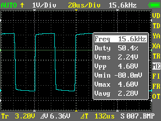
In every PWM period counter must count 256 steps, so frequency of signal is 256 times lower than counter clock from prescaler. PWM frequency = Atmega clock frequency/timer prescaler(1,8,32,64,128,256)/256. With 4 MHz crystal maximum(without prescaler) PWM frequency is 15 625Hz.
Register setup
For example 15 625 Hz, 50 % duty cycle, non-inverting mode PWM signal generation.
1. OCR2=0x80(128); As mentioned before duty cycle = OCR2/256*100%
2. TCCR2=0x69;
3. DDRB=0x08; PWM signal is outputted by toggling level of PORTB pin 3.
DDRB sets it as output.
All together:
#include <iom8.h>

int main( void )

{

DDRB=0x08;
OCR2=0x80;

TCCR2=0x69;

while (1) {};

}
Result:
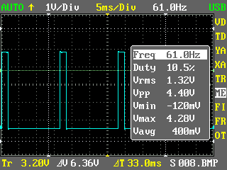
~10% duty cycle, 61 Hz.
#include <iom8.h>

int main( void )

{

DDRB=0x08;

OCR2=0x1A; // 256/10=25,6 26 in hex = 1A;

TCCR2=0x6E; // 256 prescaler
while (1) {};

}
Result:
And there is demo program and *.hex file for PWM demo seen in video.
 Atmega8 PWM demo program (1.8 KiB, 9,627 hits)